
Specification
Specification of ProGate cable. (For ProGate HW 4 Generation)
1. Port pin map
Port of ProGate cable is 9Pin D-sub. (Below is in-side view of cable and out-side view of ProGate)
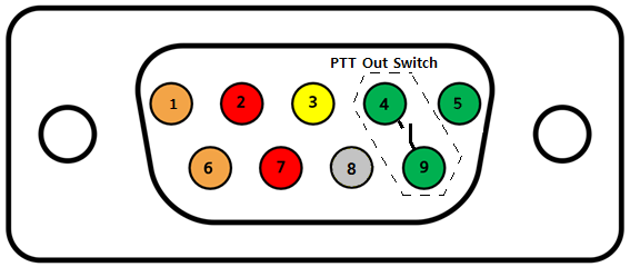
| No | Name | Desciption |
|---|---|---|
| 1 | UART(PG Tx) | Uart's tx of ProGate |
| 6 | UART(PG Rx) | Uart's rx of ProGate |
| 2 | Rx(Line-in) | ProGate's line-in. (* Notice : Max volt is 5V.) |
| 7 | PTT-IN | This is for PTT-IN signal(High or Low). (* Notice : Max volt is 5V.) |
| 3 | Tx | ProGate's right speaker |
| 8 | GND | |
| 4 | PTT-OUT switch | When PTT out is on, PTT-OUT and Base are linked. |
| 9 | Base | Base line of PTT-OUT switch |
| 5 | PTT-OUT | When PTT is locked from server, this pin is on(High or Low). High is 3V. |
2. Inside of ProGate
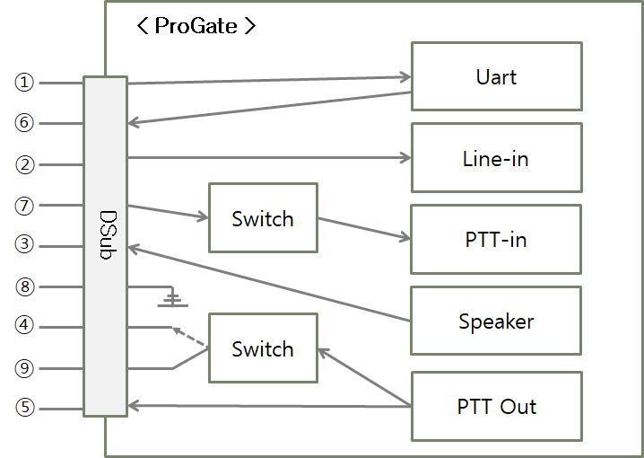
3. PTT-OUT switch operation
ProGate has a switch for PTT out. In normal status, PTT-OUT switch is unlinked. But if PTT out is on, PTT-OUT switch and Base are linked.


PTT out switch is similar with a physical PTT button. Developer can make a situation PTT button pressed by using PTT out switch.